We are Mechatronic Innovators! Contact Us
Reversal Methods & Error Separation Techniques
BACK TO OVERVIEW
Introduction
Enhancing the accuracy of measurements in dimensional metrology can be achieved by addressing and mitigating the form error inherent in your measurement reference. This enhancement is facilitated through the use of reversal methods and error separation techniques.
Reversal methods represent the most direct approach. These methods involve altering the orientation of the part under measurement and/or the measuring instrument itself. The underlying principle of reversal methods is straightforward: by conducting measurements in various configurations and subsequently averaging these measurements, form errors—which manifest as mirror images in the reversed setups—can effectively be neutralized.
In contrast, error separation techniques adopt a more complex strategy to identify and reduce form errors, without necessarily removing them completely. These techniques leverage advanced mathematical models and employ multiple measurement strategies to isolate and accurately quantify the form error.
This section delves into various spindle error separation techniques and the straightedge reversal method, providing a more detailed examination of each. The benefits and potential drawbacks of these methods are addressed, along with the underlying mathematics.
Spindle error separation techniques
The error motion of a rotary system, such as a bearing, spindle, or rotary table, is generally measured with a capacitance probe targeting an artifact as described here. The measurement data includes both the effect of the rotor’s error motion and the out-of-roundness (form error) of the artifact. For most rotary systems, the form error of a precision artifact is at least 10 to 100 times smaller than the error motion. In such cases, the form error of the artifact is neglected, and the measurement result is treated as the error motion of the rotary system. However, when the error motion is of the same order of magnitude as the form error of the artifact, then the form error of the artifact cannot be ignored. The error motion and form error can be separated by the use of an error separation technique.
1. Donaldson reversal
Donaldson reversal requires two measurements to compute the synchronous radial error motion. Both the the sensor and artifact orientation must be rotated with respect to the rotor by 180 degrees between the two measurements, i.e. M_{1}(\theta) and M_{2}(\theta). This is schematically illustrated in the figure below (note the alignment of the filled circular markers between both measurements).
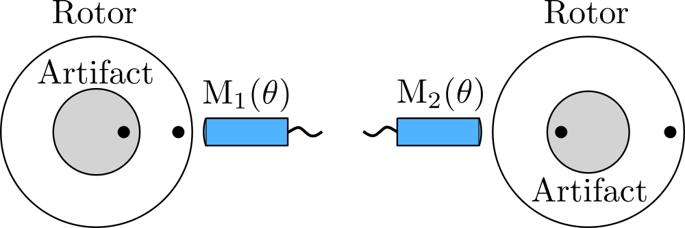
Donaldson reversal
As the sensor targets the artifact, the measurement data M_{1}(\theta) and M_{2}(\theta) are a combination of the artifact’s form error A(\theta) and the synchronous radial error motion of the spindle X(\theta). We may thus write:
M_{1}(\theta) = A(\theta) + X(\theta)
M_{2}(\theta) = A(\theta) – X(\theta)
Hence, by adding and subtracting both equations, the synchronous radial error motion of the spindle X(\theta) can be separated from the artifact form error A(\theta):
A(\theta) = \dfrac{M_{1}(\theta) + M_{2}(\theta)}{2}
X(\theta) = \dfrac{M_{1}(\theta) – M_{2}(\theta)}{2}
This method is theoretically superior to other methods as it results in perfect error separation. However, it requires high-quality hardware to achieve nanometer-level repeatability and accuracy since the sensor and artifact must be indexed with nearly perfect orientation and fixturing to measure precisely at the correct radial and axial locations between both measurements. It is apparent that there are practical difficulties involved in this process that make this method less than perfect.
2. Grejda reversal
Grejda made an improvement to the Donaldson reversal technique through the use of a high-precision indexing table and a reversal chuck, as illustrated below. The spindle under test is placed on an indexing table, rotating the stator of the spindle 180 degrees between two measurements, while the sensor is kept fixed at the same position. However, the artifact must still be indexed by 180 degrees, as is the case with Donaldson reversal. To reduce eccentricity after indexing, Grejda made use of a special reversal chuck with a lapped spherical pilot and precision-ground holes. These modifications greatly simplified the implementation of the Donaldson reversal technique as it eliminates the need for repositioning the sensor.
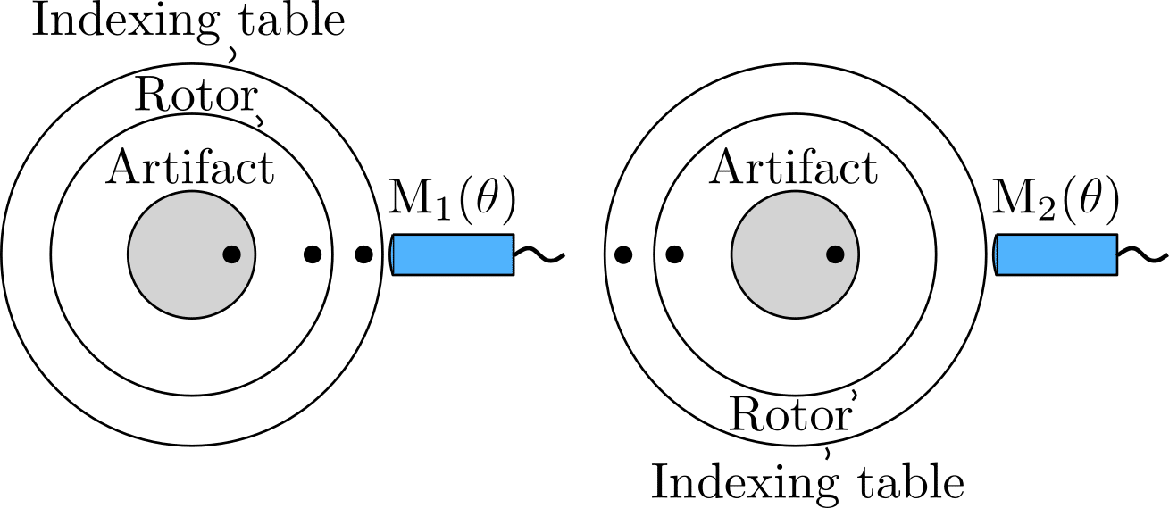
Grejda reversal
3. Multiprobe error separation
The multiprobe error separation technique originally uses three sensors that simultaneously measure S_{1}(\theta), S_{2}(\theta) and S_{3}(\theta), as shown below. Sensors S_{2} and S_{3} are positioned with respect to sensor S_{1} by an angle \alpha and \beta, respectively. This means that neither the sensors nor the artifact are moved while measuring the error motion. This is beneficial for measurement accuracy. A drawback of this method is that the sensors can have different sensitivities. Moreover, some harmonic information can be lost depending on the chosen measurement angles \alpha and \beta, resulting in a situation where the form error may not fully be eliminated. This partial removal of form error could lead to inaccuracies in the harmonic analysis of the measured data, as certain frequencies may be underrepresented or omitted entirely. This outcome highlights the necessity of careful selection and optimization of measurement angles to minimize the loss of critical harmonic information and ensure a more accurate representation of the form error.
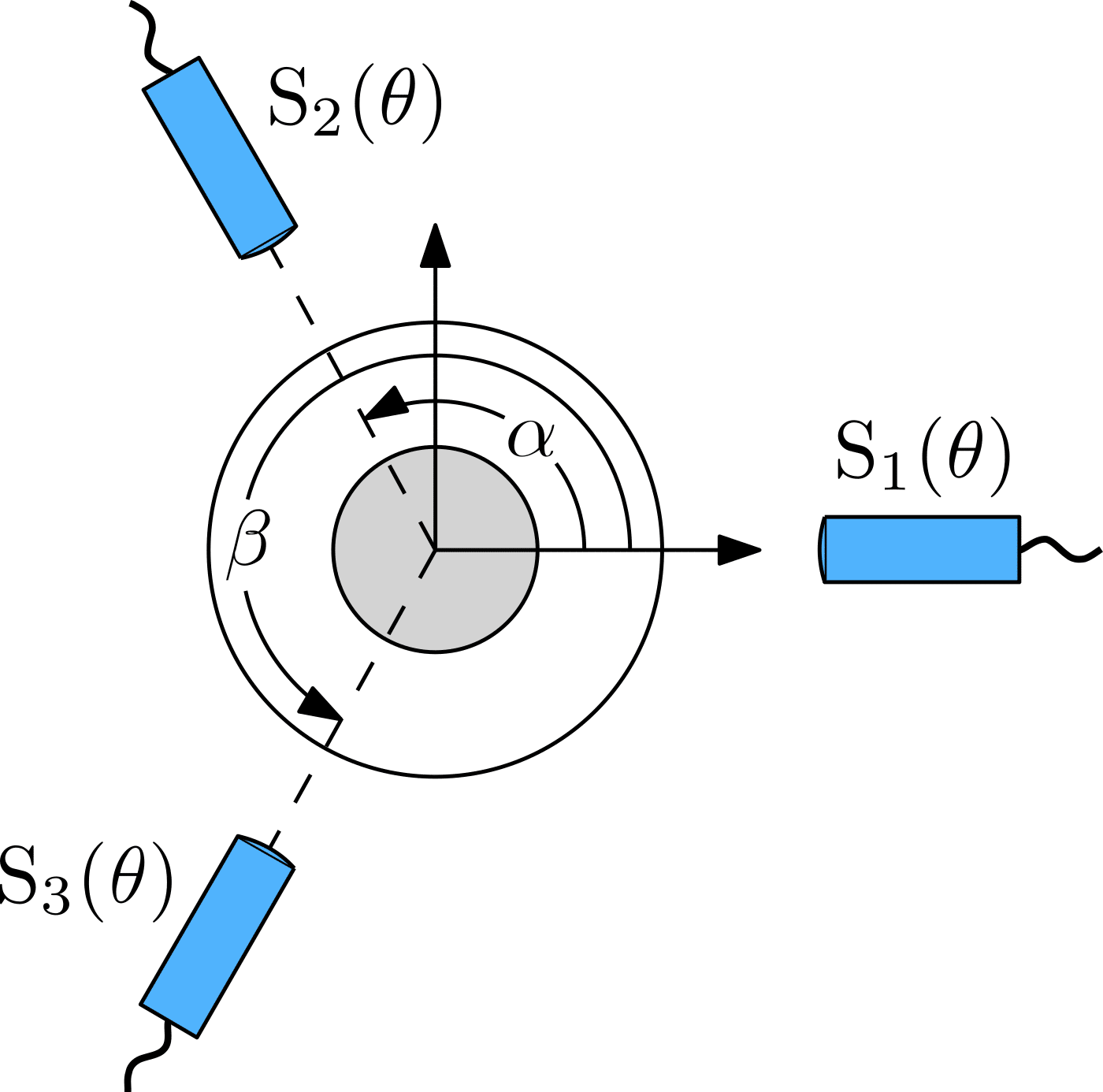
Multiprobe error separation
The sensors S_{1}, S_{2} and S_{3} measure a combination of the artifact form error A(\theta) and the X and Y-component of the radial error motion, phase shifted by the location of the sensors, i.e.:
S_{1}(\theta) = A(\theta) + X(\theta)
S_{2}(\theta) = A(\theta-\alpha) + X(\theta)\cos\alpha + Y(\theta)\sin\alpha
S_{3}(\theta) = A(\theta-\beta) + X(\theta)\cos\beta + Y(\theta)\sin\beta
By defining S_{\theta} as a weighted combination of these three measurements, cancelling the contribution of the spindle error motion X(\theta) and Y(\theta), using the coefficients of unity, a and b, we get:
S(\theta) = A(\theta) + a A(\theta-\alpha) + b A(\theta-\beta)
a = \dfrac{-\sin\beta}{\sin(\beta-\alpha)}
b = \dfrac{\sin\alpha}{\sin(\beta-\alpha)}
It may be clear that this method is mathematically more complicated than the Donaldson and Grejda reversal techniques. Moreover, the three sensors must be perfectly positioned at the angles \alpha and \beta, and the sensitivity of the sensors should not differ from each other, as this can lead to inaccurate measurements. The latter issue can be solved by using a single sensor instead of multiple sensors with varying sensitivities. In this case, the error motion must be measured three consecutive times, with the sensor repositioned by angles \alpha and \beta, respectively, between measurements. Even in this case, precise sensor positioning is crucial. Besides these drawbacks, the major advantage of the multiprobe method is that, depending on the configuration, sensor(s) and artifact remain fixed during testing.
The choice of measurement angles \alpha and \beta is important to reduce the effect of harmonic suppression. For example, when the sensors are evenly spaced every 120 degrees, low-order harmonics are incorrectly computed.
4. Multistep error separation
In the multistep error separation technique is the artifact indexed in angular increments without moving the displacement sensor. The figure below shows a schematic of the multistep method. A single sensor measures the displacements from the same orientation angle in all measurements. The measurement contains the spindle radial error motion X(\theta) and the phase-shifted artifact form error A(\theta).
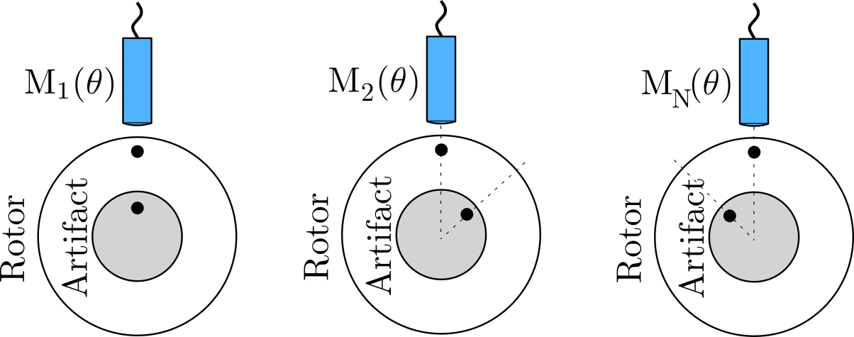
Multistep error separation
M_{n}(\theta) = X(\theta) + A(\theta + \phi(n-1)) where 1 \le n \le N
Summing each of the N measurements one can solve for the radial error motion of the spindle. However, the harmonics occurring at integer multiples of the number of measurement steps N are not correctly separated. Therefore, one should choose a sufficient number of measurement steps to ensure reliable measurements. As the accuracy of the multistep method depends upon accurate indexing of the artifact and the number of measurement steps, this method is best left for situations where it is not possible to use one of the above described methods.
Straightedge reversal
The straightedge reversal method is used to determine the straightness or flatness S(z) of a surface with high accuracy relative to a reference guideway R(z). This is illustrated below. This method employs the principle of reversing a reference R(z) along the surface being evaluated, allowing for the quantification of the straightness or flatness S(z).
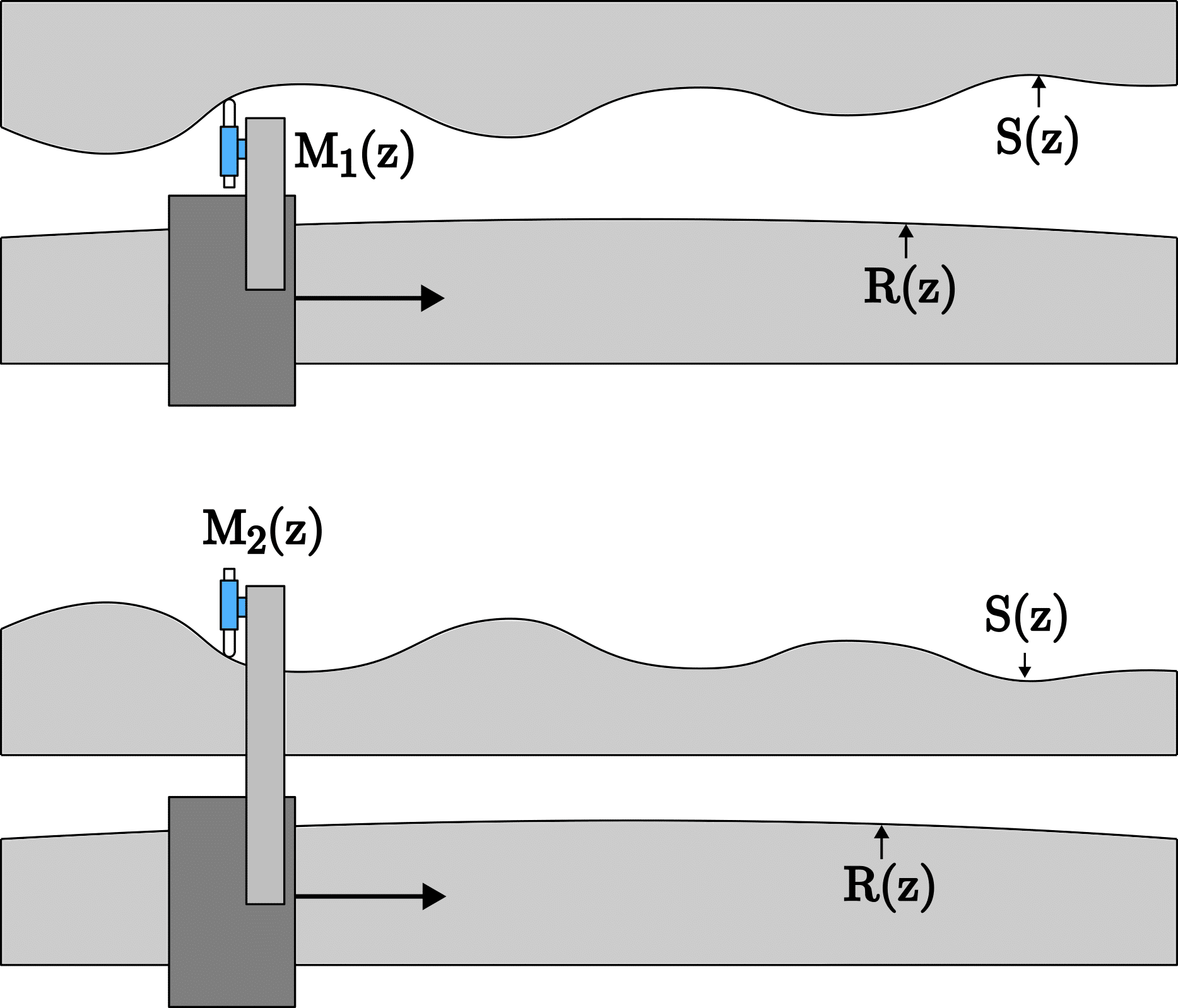
Straightedge reversal
As the sensor measures the surface S(z) relative to its reference R(z), the measurement data M_{1}(z) and M_{2}(z) are:
M_{1}(z) = R(z) + S(z)
M_{2}(z) = S(z) – R(z)
so that:
R(z) = \dfrac{M_{1}(z) – M_{2}(z)}{2}
S(z) = \dfrac{M_{1}(z) + M_{2}(z)}{2}
From the measurement of the reference, it can be determined if it falls within its specified tolerance, meaning if its deviation is minor enough to be disregarded in future measurements.