We are Mechatronic Innovators! Contact Us
Error motion
Introduction
This page describes how to specify and measure the error motion of a bearing or spindle based on the ANSI/ASME B89.3.4 standard.
Error motion
Error motion refers to the unintended movements or deviations in a rotary system from its ideal rotational path. Ideally, a bearing, rotary stage, or spindle would rotate precisely around its designated axis, which is typically defined as the z-axis in a Cartesian coordinate system. However, in practical applications, no rotary system is perfect. Therefore, any movement in the other five degrees of freedom, apart from the intended rotation, is classified as error motion. This error is a critical factor in the performance of rotary systems, impacting their precision and accuracy. Understanding and controlling this error is essential in high-precision engineering applications.
Measuring the error motion
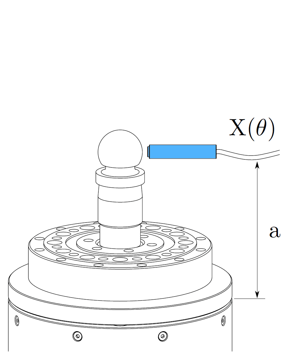
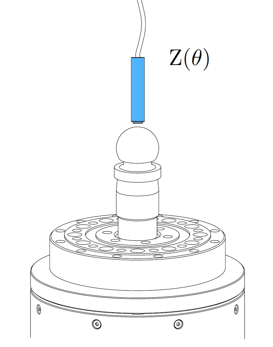
The error motion of a bearing or spindle is typically measured with a displacement indicator, such as a capacitive sensor, which targets a lapped spherical artifact (master ball) mounted to the rotor of the bearing or spindle. This setup is demonstrated below for both radial and axial error motion measurements. In most rotary systems is the form error of a precision artifact at least 10 to 100 times smaller than the system’s error motion. In such cases is the form error of the artifact usually neglected, and the measurement is treated as indicative for the error motion of the rotary system. However, some rotary systems, like an aerostatic spindle with error motions of 20 nanometers or lower, approach or even surpass the precision of the artifact. This situation requires the use of an error separation technique to differentiate between the error motion and the artifact form error in the raw measurement data. A description of these error separation techniques can be found here.
Radial error motion
Axial error motion
Eccentricity of the artifact
It should be clear that it is impossible to align the artifact perfectly with the rotation axis of the rotary system under test. The sensor or displacement indicator perceives a centering error as a once-per-revolution sine wave while measuring the radial error motion. This once-per-revolution sine wave, or 1 undulation per revolution in the frequency domain, is also referred to as the fundamental error component. In radial error motion measurements is the centering error of the artifact not considered to be an actual error motion as it can be altered by realigning the artifact. Consequently, the fundamental error component (i.e. 1 upr) is always removed from the radial error motion measurement data during post-processing. On the other hand, the fundamental error component of the axial error motion reflects a real error motion because realigning the artifact cannot remove this fundamental error. This error has a meaningful quantity and is therefore not removed from the axial error motion measurement data during post-processing.
Error motion vs. runout
In the past, the error motion of a rotary system was often referred to as runout. However, this terminology is not consistent with the axes of rotation standard, as runout also includes the artifact form and centering error, whereas error motion does not. Consequently, the error motion would be identical if both of these errors were zero. However, achieving either of these conditions is not easily accomplished.
Error motion types
The error motion of a rotary system is fully characterized by five error motion components, namely:
- Radial error motion (X(θ),Y (θ)): this is defined as the error motion perpendicular to the axis of rotation, measured at an arbitrary axial location ‘a’. The axial location must always be specified, as the tilt of the rotor influences the radial error motion.
- Axial error motion (Z(θ)): this is defined as the error motion collinear with the axis of rotation.
- Tilt error motion (α(θ), β(θ)): this is defined as the rotation of the rotor about the x-axis and y-axis, respectively. This error motion can be derived from two radial error motion measurements taken at different axial locations ‘a’.
Synchronous versus asynchronous error motion
The total error motion of a rotary system is comprised of both synchronous and asynchronous components:
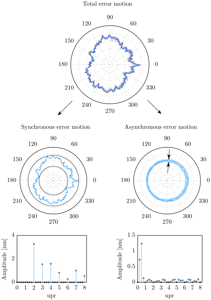
- Synchronous error motion: these errors are “synchronous” with the rotation, meaning they occur at the same angular position(s) during each cycle of rotation. Common causes of synchronous error motion include imbalances in the rotating system, geometric inaccuracies like form errors, or deformation due to uneven load distribution. They are typically represented by harmonics of the rotational speed and can often be measured and characterized in terms of their frequency relative to the rotation speed. The synchronous error motion can be obtained by calculating the average error at each measured spindle angle θ over several revolutions. In mathematical terms, this is defined as the error motion which is composed of the integer multiples of the fundamental frequency as depicted in the left frequency spectrum in the figure below (radial error motion of an aerostatic rotary table).
- Asynchronous error motion: refers to errors that do not correspond to the rotational speed or repeat irregularly during the rotation. These errors are not tied to specific angular positions in the rotation cycle and can appear randomly or vary from one rotation to the next. Asynchronous errors might be caused by factors like random vibrations, external disturbances, wear, thermal expansion, etc. Asynchronous errors are less predictable and more challenging to characterize than synchronous errors because they do not follow a consistent pattern or frequency relative to the rotation speed. The asynchronous error is equal to the remaining content of the total error motion when the synchronous error motion is subtracted. It is composed of the non-integer multiples of the fundamental frequency as depicted in the right frequency spectrum in the figure below (radial error motion of an aerostatic rotary table).
Data processing to determine the synchronous and asynchronous error motion of a rotary system can be performed either in the time domain or the frequency domain. Given that most numerical computation software, such as Matlab, is equipped with built-in functions for frequency transformations, it is often more convenient to conduct these analyses in the frequency domain as one can relate the data more easily to geometric characteristics of the rotary system from which we can determine its failing frequencies, such as the cage rotation frequency of a ball bearing.
Error motion value
Error motion measurements are most effectively graphed on a polar plot. This method of representation often reveals useful information about the rotational accuracy of the rotary system and its design. Furthermore, the values of the total, synchronous, and asynchronous error motion can be determined from this graph. Specifically, these are calculated as the differences between the radii of two concentric circles that enclose the respective error motions. For error motion assessments, the center of the least squares circle (LSC) is the preferred reference point in the polar plot.
The value of the synchronous error motion is determined by subtracting the radii of the minimum circumscribed circle and the maximal inscribed circle of the synchronous data, both centered on the common LSC center. On the other hand, the asynchronous error motion value is obtained from the largest peak-to-valley range within the asynchronous data, considering each angular position individually. In the figure above, the maximum band of the asynchronous error is indicated by two arrows.
Sensitive direction classification
A displacement indicator typically has one sensitive direction. For instance, the probe targeting the lapped spherical artifact in the first figure is sensitive to displacements normal to its sensing electrode, while it is relatively insensitive to motions in the other two degrees of freedom. In spindle error motion measurements, the measurement setup can vary: either the measurement surface (artifact) is rotated relative to a fixed probe, or the probe itself is rotated relative to a fixed measurement surface (such as a cylindrical bore).
In the first scenario, the sensitive direction of the probe remains fixed in relation to the stator of the spindle. Hence, the error motion measured in this setup is described as ‘fixed sensitive direction error motion.’ In contrast, in the second scenario, the sensitive direction of the probe is not fixed but instead rotates with the rotor of the spindle. This is termed ‘rotating sensitive direction error motion.’
It should be clear that the method chosen for measuring the error motion of an axis-of-rotation system, whether with a fixed or rotating probe, can significantly influence the error motion value and its interpretation. In spindle metrology, measuring the fixed sensitive direction error motion is common. However, a rotating sensitive direction measurement is more complex and less intuitive due to the challenges in implementing a proper spindle error motion separation technique and managing cables.
Specification of an axis-of-rotation error motion
The terminology described above is unambiguous. Yet, for a complete description of an error motion measurement, the following information is required:
1. Error motion type: specifying whether it is axial, radial, or tilt.
2. Type of error motion: determining whether it is total, synchronous, or asynchronous.
3. Sensitive direction: indicating whether it is fixed or rotating.
4. Orientation angle of the displacement indicator: this should be relative to a specified location on the stator or rotor.
5. Rotational speed and number of spindle revolutions.