We are Mechatronic Innovators! Contact Us
Air bearings
BACK TO OVERVIEW
Introduction
The rotational accuracy of an axis-of-rotation system depends significantly on the bearing technology. Three major bearing technologies exist: rolling-element bearings, fluid film bearings, and magnetic bearings. Rolling-element bearings are the most widely recognized. Today, rolling-element bearings find applications in a wide range of industries, from electric motors to gearboxes. However, imperfections in the inner and outer races, as well as variations in ball sizes and spherical shapes, make rolling-element bearings unsuitable for precision applications at the nanometer level (i.e. < 100 nm).
In fluid film bearings, unlike rolling-element bearings, there is no contact between the rotating and stationary parts. Although fluid film bearings come in various types and forms, the basic operating principle remains consistent. A fluid is introduced by an external source into a narrow gap formed between the two bearing surfaces, which are guided by the bearing itself. These two components are physically separated from each other at all times.
In the case of an aerostatic bearing, often referred to as an externally pressurized gas bearing or externally pressurized air bearing, pressurized air is supplied between the bearing surfaces through one or more restrictors. Due to the low viscosity of air, friction losses and associated heat generation are virtually eliminated, making them well-suited for demanding precision applications.
On the other hand, hydrostatic bearings involve injecting a high-pressure fluid (typically oil) between the bearing surfaces. The low, consistent, and predictable friction, combined with their high load capacity and stiffness, makes them highly suitable for precision production machinery. However, many precision applications require a pristine environment free from contamination. Consequently, this type of bearing necessitates additional precautions, including the use of seals and a circulatory system. This can be seen as a disadvantage when compared to aerostatic bearings.
Magnetic bearings, in contrast, support and move a load using magnetic levitation without any physical contact. This permits relative motion without wear and results in very low friction, similar to a fluid film bearing under normal working conditions. However, as predicted by Earnshaw’s theorem, passive magnetic bearings are unstable. Consequently, active magnetic bearings, which consist of electromagnets and a control system, are necessary for the stable magnetic levitation of a load.
Given these arguments, an increasing number of machines and measurement equipment are opting for aerostatic bearings to achieve precise motion and positioning of loads.
Orifice-compensated journal bearing
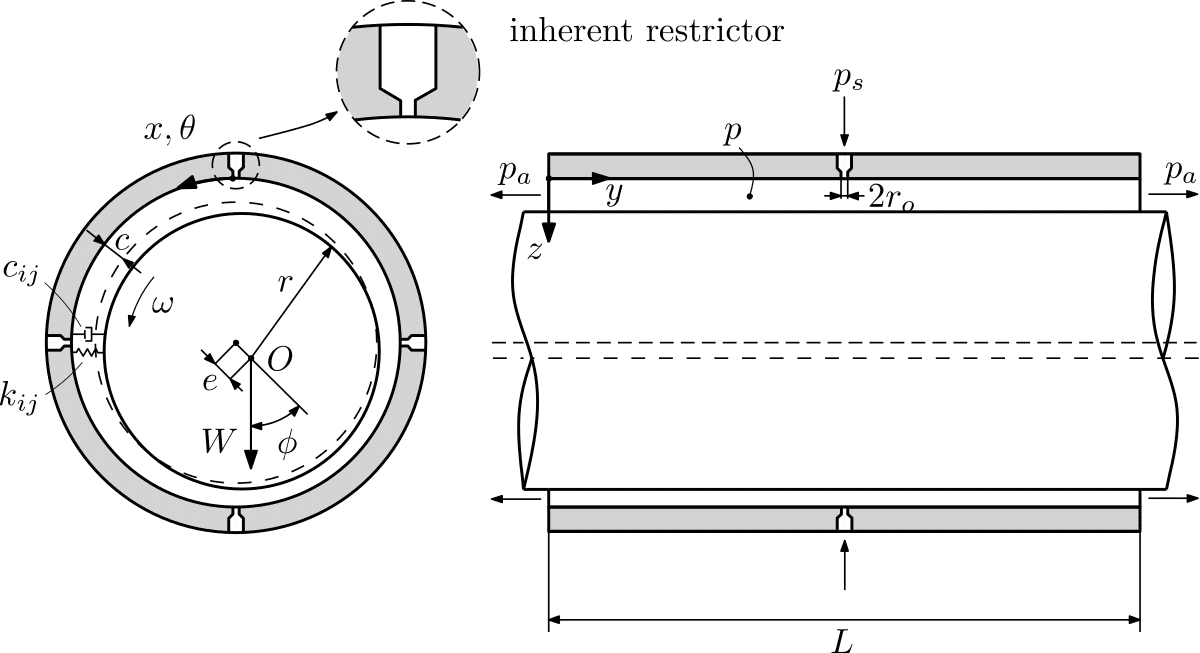
Orifice-compensated air bearings are the most widely known type of air bearings. The figure below illustrates the notation for an orifice-compensated journal bearing configuration, featuring parameters such as radius r, length L, and radial clearance c. The coordinate system (x, y, z) is anchored to the stationary housing. The inherent restrictors (typically a single row centrally placed) have a relatively small entrance radius r_o, typically ranging from 0.025 mm to 0.5 mm or more, depending on the design parameters and dynamic characteristics of the aerostatic bearing.
Orifice-compenstated journal bearing
Pressurized air, supplied at an absolute pressure p_s, enters the bearing gap c through the restrictors and gradually decreases in pressure p as it flows towards the atmosphere p_a at the bearing ends. The primary restriction in this feeding system occurs at the annular curtain area of the gap entrance.
The working conditions are influenced by the rotational speed \omega and the location of the rotational center O, which is determined by the steady-state eccentricity e and the attitude angle \phi. The resulting film force W supports the rotor and establishes the load-carrying capacity of the air bearing.
The dynamic behavior of the gas film, including the film stiffness k_{ij} and film damping c_{ij}, can be modeled as a discrete spring-damper combination. These properties depend on both the steady-state and dynamic working conditions.
1. Feed flow
The flow in the orifice is characterized by the fast acceleration of the flow from stagnation (pressure p_s) up to gap entrance (pressure p_o). The flow in this region is purely inertial or inviscid. As the actual pressure distribution in the feed flow region is of no interest for most bearing designers it is typically modeled as a lumped parameter model. The basis of such a model is found in the orifice/nozzle formula and not further described here.
2. Film flow
The flow between the bearing surfaces can be described by the well-known Reynolds equation, which is derived from the viscous flow and continuity equations. For
a two-dimensional Cartesian coordinate system, assuming a constant pressure across the fluid film h and an isothermal behaviour, the time-dependent Reynolds equation can be expressed as:
\nabla ~\cdot ~ \left[ \dfrac{ph^3}{12\mu} ~\nabla p – \dfrac{1}{2} ph \boldsymbol{V_t} \right] = \dfrac{\partial}{\partial t} \left( ph \right)
Porous gas journal bearing
In recent years, the use of porous restrictors in aerostatic bearings has gained significant popularity. These restrictors offer advantages such as higher load capacity, stiffness, inherent design simplicity, and lower initial cost, making them a promising alternative to orifice-compensated bearings. An additional benefit is the filtering effect of the porous media, which prevents small particles from passing through the narrow bearing gap, thereby extending the service life of the bearing.
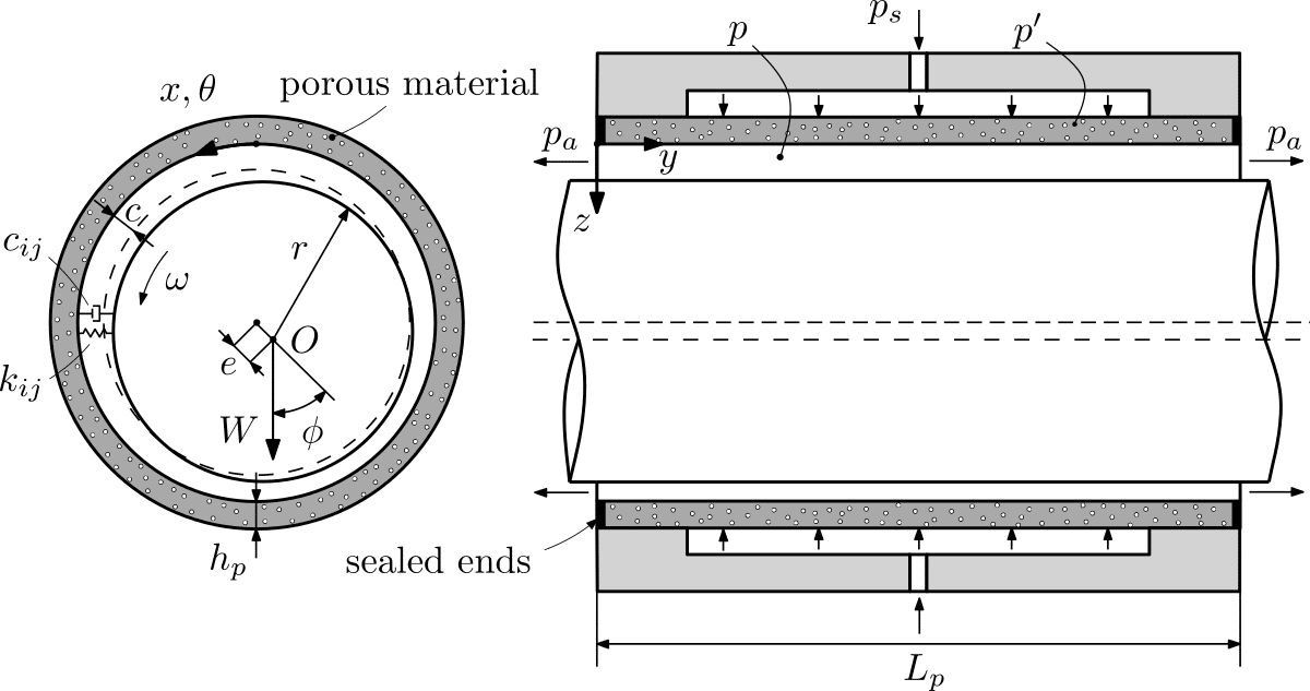
The figure below presents a schematic representation of a porous gas journal bearing. In this design, gas restriction occurs within a porous material, such as graphite, sintered metal, or ceramic, rather than through a conventional restrictor. The permeability of the porous material typically falls within the range of 1E-14 and 1E-16 m^2 to ensure optimal static and dynamic bearing characteristics, while the porosity is typically around 20%.
As depicted below, pressurized air at a constant supply pressure p_s is introduced from a plenum through the porous material, which has a length L_p and thickness h_p. Within the porous media, the air pressure decreases to p', and it further drops to p within the bearing gap c. Finally, the air is exhausted into the atmosphere p_a at the bearing ends. The bushing ends are sealed to prevent any end leakage.
Porous gas journal bearing
1. Feed flow
The flow through the porous media can be described by Darcy’s law. This is an expression of conservation of momentum that can be derived from the Navier-Stokes equations via homogenisation. For a one-dimensional flow and in the absence of body forces, Darcy’s law may be written as:
Q = \dfrac{-k_p A}{\mu} \dfrac{\partial p^{\prime}}{\partial z}
in which Q is the volumetric flow rate, A the cross-sectional area and k_p the permeability of the porous media.
Supposing a uniform and isothermal process, obeying the ideal gas law and assuming the permeability coefficient of the porous material to be constant the flow inside the porous body and in particular the pressure distribution p′ is given by:
{\nabla}^2 p^{\prime 2} – \dfrac{2 \mu \phi}{k_p} \dfrac{\partial p^{\prime}}{\partial t} = 0
2. Film flow
The fluid flow in the bearing gap of a porous bearing can also be described by the modified Reynolds equation, taking slip flow at the film-bearing interface into account:
\nabla ~\cdot ~ \left[ \dfrac{ph^3}{12\mu} ~\nabla p (1 + \Phi) – \dfrac{1}{2} ph \boldsymbol{V_t} (1 + \Psi) \right] = \dfrac{k_p}{2 \mu} \dfrac{\partial p^{\prime 2}}{\partial z}\bigg|_{z=0} \dfrac{\partial}{\partial t} \left( ph \right)
in which:
\Phi = \dfrac{3 \left(\sqrt{k_p}h + 2\alpha k_p \right)}{h \left(\sqrt{k_p} + \alpha h \right)}
\Psi = \dfrac{\sqrt{k_p}}{\sqrt{k_p} + \alpha h}
are two dimensionless parameters that account for the effect of slip flow at the film-bearing interface and where \alpha is a dimensionless slip coefficient that depends on the material characteristics of the permeable material and not on the physical properties of the fluid.